Pyronica is composed of two functional systems: the control system and the gas supply system. These systems intersect at the solenoid valves that release propane into the pipes to voice them. The organ is separated from the control station (and everything else) by a 10-foot safety perimeter, and from the fuel supply. Then there's the pipes and how they are voiced with propane. This is where the science is, since (afaik) nobody else has made a pipe organ that can successfully be played as a musical instrument.
Control System
TL;DR: MIDI - Raspberry Pi - Python - I2C - relays - solenoid valves
The controls start with a MIDI note source. This is usually a MIDI keyboard connected by USB to the control computer. We started with a Bluetooth connection, but that got flaky with a crowd of people with Bluetooth phones in their pockets. MIDI files are sometimes played for demonstration purposes. "March of the Gladiators" has a good carnival feel about it. Pyronica has also been played over the internet using RTP-MIDI, although the feedback for the person playing can get delayed.
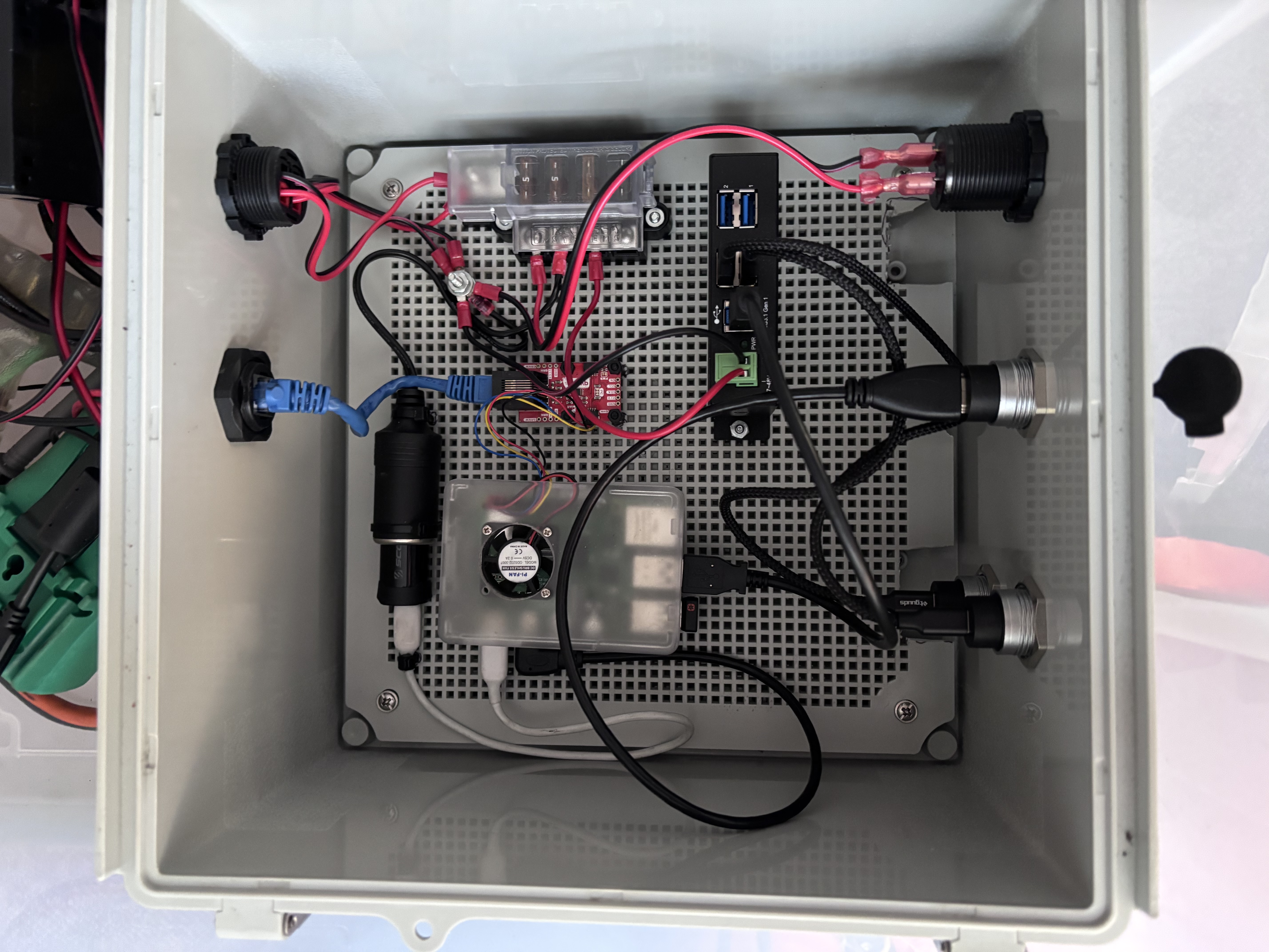
The control station computer box
The control computer (there's always a computer, isn't there?) is a Raspberry Pi running a short Python program that leverages the host's MIDI support for the source. I wrote a MIDI "instrument" that converts the MIDI note on/off messages into I2C messages. These messages are sent via a differential driver over an Ethernet cable to the organ control box with I2C relay boards. These relays actuate the solenoid valves that allow the propane into the pipes.
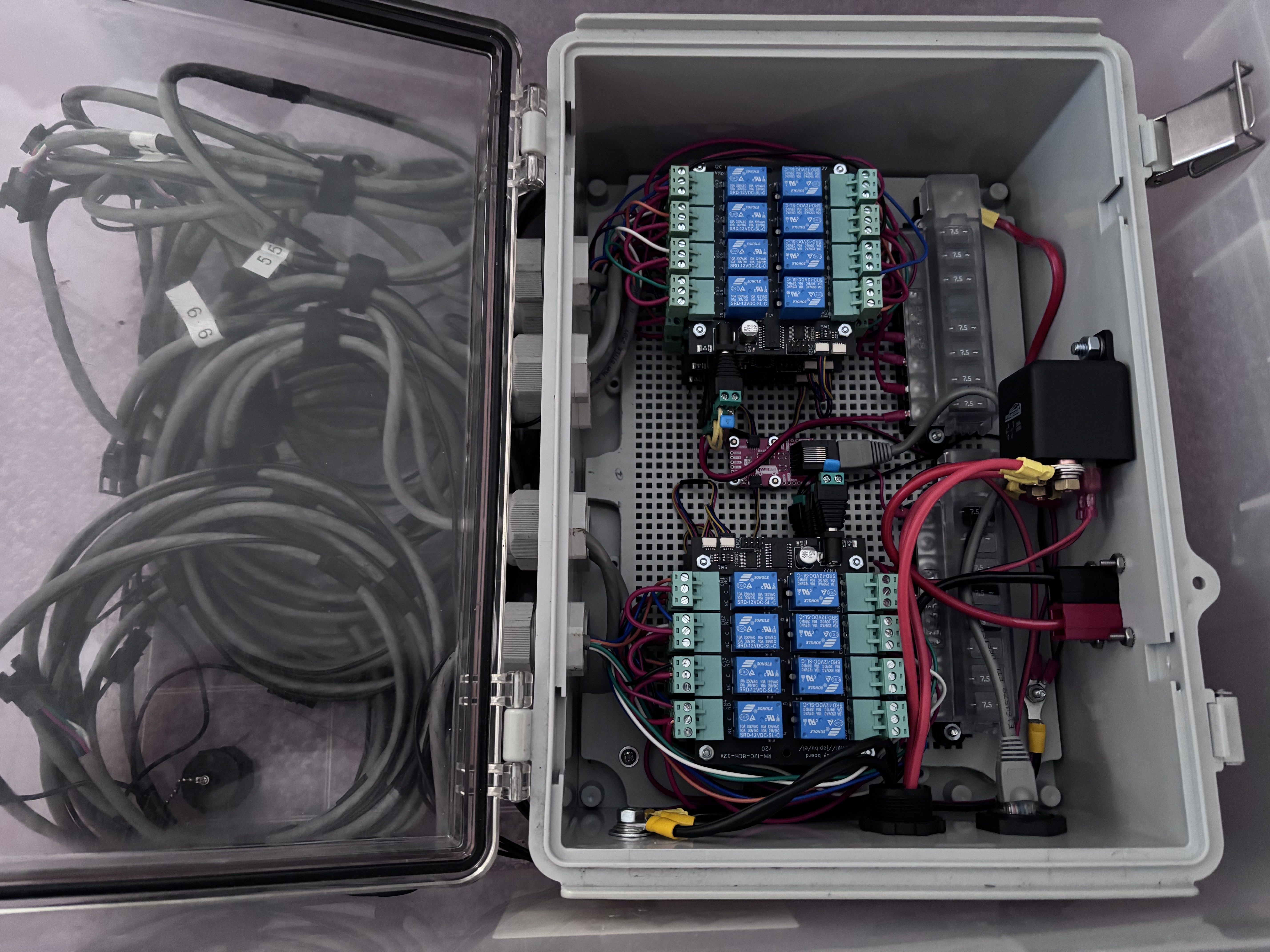
The organ control relay box
Gas Supply System
With the addition of a third lower-note (bigger-pipe) octave, 20lb. barbecue grill tanks no longer cut it, and I had to move to 100lb. tanks. Pyronica currently uses two 100-lb tanks, each heated with an 800W barrel heater to keep it from freezing up. One tank supplies the upper two octaves; the other supplies the lower octave. The propane is fed through two 40-foot hoses with 3/8 inch flare fittings. (They're the best -- almost never leak!).
The upper two octave system is fed through a cascading pair of residential pressure regulators to deliver about 0.4 psi (8 inches w.c.) into the supply manifold. The low-pressure regulator is limited to about 1.2 million BTU/hr, which turned out not to be enough to run all three octaves. So the low octave is supplied separately with a larger low-pressure regulator. This turned out to be a good thing, because the lower pipes needed to run at about double the manifold pressure of the higher octave. This required replacing the pressure adjustment spring with a stiffer one. These regulators feed manifolds that distribute the gas to the pipes and solenoid control valves. The manifolds are custom brazed to how I wanted them, and powder-coated bright red.
The solenoids depressurize the manifold much faster than the basic 325-7 regulator can respond. This pressure drop causes the pipe to start at full volume but then get quiet for about a second while the regulator catches up. Of course the note is often over by then, overshooting the target pressure. The first try was using a 20lb. propane tank as an accumulator tank. (It has a 3/4" NPT connector for the valve.) This helped, but wasn't enough to fully dampen the pressure swings. Ruuska suggested a "gasometer" design, which uses water to change the volume of the accumulator. As the pressure drops, the water head drops and the volume gets smaller, maintaining the pressure better than a rigid container. This works quite well. The 210-D regulator is a "balanced" design, which is better in every way except price. It is about the same size, has 5x more flow capacity (BTUs/hr), and responds much faster than the basic regulator according to the pressure gauge I stuck on the large-pipe manifold. I haven't bothered with a pressure compensator for this octave yet and it sounds okay. A rigid expansion tank might be all that's needed to smooth out the higher-frequency pressure swings.
The pipes
The fundamental challenge with organ pipes blowing anything other than ambient air into them is that the speed of sound in that medium is different in that medium than it is in air. The frequency (pitch) of the pipe is determined by the speed of sound in the medium divided by the length of the resonant chamber. Lengthening the pipe lowers the pitch, and this is how the pipe is tuned. The speed of sound in propane is about 80% the speed of sound in air, due to its higher density. This means that a pipe full of propane is about 2-1/2 semitones lower than the same pipe full of air. And a mixture of air and propane voices at an in-between pitch. Keeping the contents of the pipe stable is critical to maintaining a stable pitch when voicing.
Early versions of Pyronica were built without this understanding. Vertical pipes filled with propane over a second or two as the note is played, causing the pitch to drop significantly. When the note ends, the propane drains out of the pipe and the whole effect starts over. The first major improvement was simply to rotate the pipes so they were horizontal with a smaller mouth facing only up. This helped enormously, but it still took playing to fill the pipe with propane, and it tended to leak out over time if not played. The second major improvement was to provide a small constant feed of propane into the midpoint of the pipe. This keeps the pipe much fuller of propane at all times. Wind is still something of an issue, but under quiet conditions it can be quite stable as the video from the woods environment shows. If you're interested in this aspect, see the pipe tuning challenge in the "Get Involved" section.
Traditional organ pipes have a length about 11 times the inside diameter. For propane, the sweet spot seems to be around 8 to 10 times. All of Pyronica's pipe windways are about 1mm wide, across a mouth that goes about 90 degrees around the pipe. I'm told the lower notes (with fatter pipes) should have a somewhat wider windway. It only makes sense that tiny pipes should have tiny windways, but I have not yet experimented with this. The relationship between supply pressure, windway width, and mouth height (cut-up) is given by Ising's formula.